What is it?

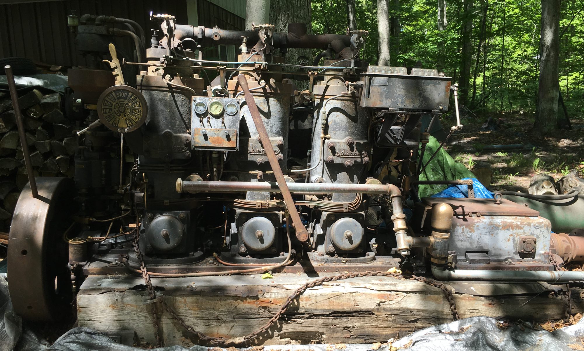
It’s been a lot of fun to figure out what everything is on the engine, particularly the little details. Lots of clever engineering. But I’ve been stumped by this one:

It protrudes into each crankcase above and a bit offset starboard from the crankshaft. Not shown is a jamb nut.

I’m sure there will be some old-timers who will see this and immediately say ‘you dummy, of course that’s the …. ‘. But I couldn’t figure it out. It didn’t touch the crankshaft. It couldn’t be anything electrical. Obviously deliberately offset with the ability to position as desired. It took a buddy coming over to have a couple beers in the shop to figure it out. By rotating the crankshaft he recognized that the piston nearly touched the brass “probe” at its lowest travel point. The outside bass rod is shaped like a whistle but it appeared to be solid inside. Then the light came on. It has to be a whistle.

Some may frown at this but I was curious. I could not resist the temptation to prove it. I rotated the “probe” (I still don’t know what it’s called) so the pin was at the top. Then I rotated the crankshaft and sure enough it sheared off the inside pin leaving a hollow body. Normally the inside brass rod is adjusted so it just barely clears the piston. If there was significant wear in the rod bearing there would be additional travel in the piston and it would shear off the inside pin. The outside brass pin that has the whistle cut is actually a tube with another pin pressed inside. That inside pin has a small beveled edge so air (crankcase pressure) could pass through and alert the operator of a problem before a catastrophic failure. I tried it with compressed air and the whistle is loud!

A brilliant and simple solution to an engineering challenge.

I have not seen this feature on the other Kahlenbergs I’ve looked at and it isn’t in my parts diagrams nor referenced in my copy of the operating manual. The crankcase is cast with provision for this specific mount point so it obviously came from the factory this way. Perhaps it was an option or something found on earlier engines (mine was made in 1946, not exactly early but about midway through the manufacturing life). The one I tested likely would not have worked because the internal hollow body was packed with corrosion and crud. That may be why I haven’t seen others.

I will remake the inside brass piece by threading and counter-sinking a 3/8″ brass rod.
Piston removal

After discovering one bad main bearing I decided that it would be prudent to get a look at all of them along with the rod bearings. There is more to the babbitt bearing story but that will come in a future post. I removed the cap for #4 behind the #3 cylinder. The top bearing half looked in good shape. I spun out the lower bearing by lifting the rear of the crankshaft slightly to take off some of the pressure. It spun out easily using a cut-down snowmobile hifax and rotated the bearing out. The lower half is okay condition but has suffered some scuffing. At a minimum it will have to be scraped but perhaps repoured.

#4 bearing
Lower and upper #4 bearing halves

Interesting to note that these bearing halves were repoured at some point. They are numbered #4 and #6 on both. Since this bearing is unique in the “A” series motor as being behind the last cylinder, the bearing would have originally come from a 5 cylinder engine.

Since line-boring will need to be done with any replaced bearings, it was made clear that the engine will need to be disassembled to the main foundation. For no particular reason I started with the #2 cylinder. The prior machine shop had been asked to remove the top ring ridge so the piston could be removed without damaging the rings. They didn’t do a very good job so I had to do a little hand grinding. It would be nice to have a proper reamer but finding one for a 8 1/2″ bore is tough without paying a lot of money. With that done I cleaned up the threaded hole in the center of the piston and installed an eye-bolt for lifting.

#2 piston coming out
#2 piston
#2 piston
#2 piston

The piston and rod are heavy. I’m guessing well over 100 pounds. This one was grimy and full of carbon but overall looks very good. The rings are in surprisingly good condition. Mill marks are still partially visible. I cleaned up the rings and scraped off most of the carbon in the ring groves. I made some carts to assist with safe movement and storage of the large components.

Rings from #2 piston after cleaning

Next up is pulling the cylinder and top case half. I fabricated a crude but functional cylinder lifting jig out of materials on-hand. These parts came off easily.

I recently removed the #1 piston. This one has a little bit of rust on it along with a partially stuck ring. The ring freed up fairly easily and I think the piston will clean up fine. I removed the rings, cleaned and lubed them. They look very good.

The rods are a three piece design with separate top and bottom bearings. The number two top bearing babbitt is heavily damaged. It looks like there may have been too much slop at some point and the ignition slamming beat on the bearing. The damage is centered around what would be just past top dead center, i.e. fuel ignition. This babbitt will have to be rebuilt. I was very surprised to see .090 worth of shims on each side. According to the manual these bearings are supposed to have .010 oil clearance which seams like a lot for 3.75″ diameter shaft. The operating engineer could remove a shim or two as the rod bearing wore. It’s really neat to see the things the designers did to make field repairs very simple.

#2 rod bearings
Top rod bearing half from #2 piston. Note the cracks.
Looking down #2 cylinder