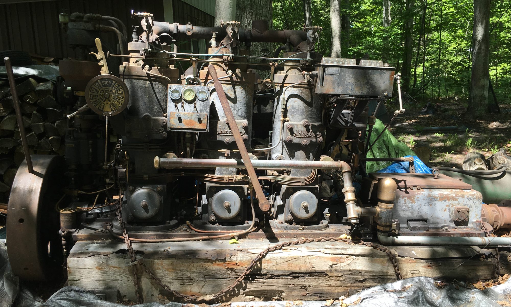
We poured new babbitt for the #4 and #5 bearing shells so I was anxious to start the cutting process with the line bore. First I had to clean the shells to get the excess babbitt material removed and properly fit the bearing shell halves. I tried a combination of coarse files, disk sander and even a router (I’m a recovering carpenter). This was a bit tedious because I had to be very careful to not damage the bronze shells. I’d like to know what process was used originally at the factory to accomplish this task.
Once cleaned up, I mounted the #5 bearing shells with the new gaskets Kurt made and torqued the bolts. The shells are held in consistent alignment with taper pins on either side of the top shell.
The cutting tool is mounted in the boring bar and held with a set screw. A very accurate depth gauge is part of the line bore kit and is used to set and verify the cutting tool.

And then we cut! The rough passes took .025″ of material and at the highest cut rate, which I believe is .010″ per revolution. We had no issues with chatter. We checked measurements as we went and everything was spot-on.


We took much smaller cuts with the last two passes. We also used a finer cut of .005″ per revolution for the last cut of just a few thousandths. The bore is cut .005″ over the crankshaft diameter (3.750″).

That’s two down and three to go with the line bore.


