Flashback – The Retrieval

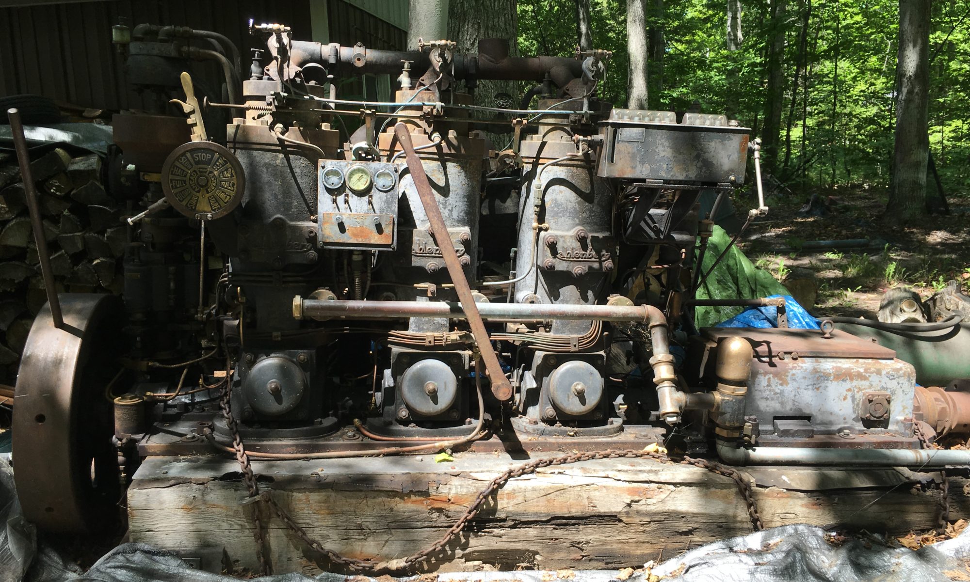
Taking a break to answer a question that comes up somewhat frequently: How did you get the engine here? It wasn’t easy. As it sits, the Kahlenberg weighs a little north of 7000 pounds. After the purchase was agreed to in October of 2016, I had no good idea how I was going to get it out of Larry’s yard where it had been sitting since 1985. The engine was on large timbers but those timbers were rotting along the ground. Hiring a rigger was the logical choice but obviously there would be significant cost. Plus I’d have to hire another rigger once I got it back home to get if off the trailer and into my shop.

I did a lot of google searches. Some guys had some clever ideas for moving things but every option seemed to have at least one large negative for my specific need. The idea came to me after a few weeks. Make the engine into a big Radio Flyer. I just needed to design it so the engine didn’t have to be lifted any higher than necessary. It also had to be somewhat maneuverable. Getting it out of the yard required a tight S-turn to avoid trees and line up with the driveway so it could be hauled onto a trailer.

I started with the List of Craig. I found a couple axel sets complete with rims and tires used for moving mobile homes. These have the benefit of being rated for 6000 pounds each plus are relatively cheap because they aren’t made for continuous use. The next stop was Discount Steel to get materials to make the frame. Most of the smaller parts came from Fleet Farm. I made angle brackets for the rear axel that would support the engine beams. The front needed to be steerable so, like the Radio Flyer, I made an axel with a single center pivot bolt that mounted to a large plate. The plate would mount to the bottom beams at the front of the motor via lag screws. The beam was polished and greased to make it steer easily. The original mobile home axels were cut. The wheels had to be able to mount individually from each of the four corners. Again, I didn’t want to get the engine too far up in air. Tie-down rings were welded onto each of the corners for steering and securing while trailering.

building the ‘radio flyer’

I loaded up the Radio Flyer components onto my trailer along with every tool I could possible think I’d need. It was a full truckload. We moved a lot of stuff that was in the way and raked out all the leaves and debris. Then the jacking process began. The ground was soft. I tried to be very careful but this is one thing I would have done differently. I let myself get too rushed and didn’t secure the base of the jacks as well as should have been done. That led to the damage that was outlined in a prior post. But eventually I got the motor up high enough to mount the Radio Flyer. That part of the job went very well. The design worked!

jacking up the motor
up on wheels

Next we used a pickup to snake the Kahlenberg out of its 30+ year home. The unit steered easily and we got it lined up with the trailer without an issue. The next job was to winch it on. I didn’t have a better way to get it on the trailer other than using come-alongs. It took a while and a bit of sweat but it worked.

steering it out of its long-time home

The tow home was uneventful. It didn’t move a bit. Getting it into the shop required a reversal of the process (that’s another story). The Radio Flyer served its purpose very well and it cost me less than $400. It was used a second time to load up for a trip to the machine shop and then to the new shop after our move. The parts are stored now and could be used again if needed.
Bad rear bearing

I’ve wondered why the Kahlenberg came out of the Faith when it did and now I have a pretty good idea. The last bearing to be inspected was the #5 tail bearing where the thrust plates are located. The babbitt bearing is shot. It appears to have failed due to lack of lubrication. Also, the thrust roller bearing is flat-spotted badly. It’s likely this bearing got very hot, despite being water cooled, and partially melted. It had to have made quite a sound under load.

#5 babbitt bearing, or what’s left of it
Top half of babbitt bearing
Roller thrust bearing

I’ll clean these up as best I can but this setback will require a new plan.

Oilers

The engine deep clean continues. The transmission was a mess but has cleaned up well. I doubt I’ll disassemble the transmission so this might be it unless I find anything functionally wrong. There might be a way but I can’t see how the transmission can be removed without lifting the crankshaft and that isn’t in my plans if I don’t have to.

Partially cleaned
After cleaning
Water pump crankshaft bearings

After cleaning up the transmission casing it was time to move onto something else. One of the unknowns that could decide whether this engine runs again is the condition of the oilers. These two Madison-Kipp oilers provide most of the lubrication. They are a bit complicated and an ongoing concern has been their condition. If water had made its way into the oilers it might be a real challenge so I decided to start in on one of them. I started with the one that looked more rough.

There are 10 oil lines from each of the two pumps. The flow rate is adjustable for each oil line. This is technology that had been well established when this engine was designed and built. Madsion-Kipp oilers were found it many applications including industrial and steam. The company is still in business. I was able to download documentation for the oilers although spare parts are long gone. Oil is stored inside each of the oilers and can be manually filled or plumbed in from a large oil tank as I’ve seen in some fish tugs and other applications.

I drained the oiler and found some water but fortunately no rust. But the oil was a nasty blobby mess that would not completely drain out. I started the process of disassembling the oiler with some trepidation giving the complexity of these mechanisms.

Oiler mechanism
sludge
Eccentric oil pump mechanism
Oil pump

You can see on the last picture how the sludge has clogged the inlet screen on the oil pump. But appears to be in otherwise very good condition. So far I don’t see any issues with the oiler at all other than the need for a thorough cleaning and new cork gaskets for the covers and sight glass.

Putting this back together will be a challenge but I think I have it figured out. There is some very cool engineering in this assembly. The eccentric parts only go together one way so all I have to do is keep each of the sub-components indexed. This will keep me busy for a bit. I did find quite a bit of wear on the brass eccentrics closest to the index gear but they should work okay.

Here’s hoping it all goes back together.

oiler parts
oiler parts

Cleaning

I probably should have done this before but finally doing detailed cleaning on the core engine. A fair amount had been done but not a thorough job. A lot of time has been spent debating about painting. Righ now I’m inclined to leave the engine as-is without doing much painting. I really like the “old” look. It’s authentic. You can see the stories just looking at it. Patina. Steampunk. Whatever you want to call it. It will be more difficult but I can always paint it later if I change my mind. I went over the engine with a coarse wire brush just to get the loose paint off then a quick wash down with mineral spirits. I wasn’t sure how it would look but I think it’s okay.

After a quick going-over with a wire brush

Now I’m working on cleaning up the lower part of engine that had not been thoroughly cleaned before. This involves partially disassembling the bearing caps. I may pull these off anyway for inspection and pre-lubrication. Tools of the moment are basic: various wire and plastic brushes, dental picks and even an old Smith Corona typewriter brush. And lots of paper towels and mineral spirits. Some of the gunk is like hardened tar and only comes off with a bit of encouragement. This may not sound like fun, and it isn’t, but it is way better than dealing with rust.

Cleaning the lower parts of the engine including the bearing caps.

This cleaning will take some time but then I’ll start working on rebuilding some of the removed sub-assemblies. I’m keen to take a look at the oilers.

Front bearing

View of crankshaft and timing gear with front bearing removed

I restarted the project with the forward bearing and the base of the governor tower. Dry fitting some of the repaired castings shows that the fit isn’t great. The gear housing isn’t flat. Some shims and gaskets should make it okay. Luckily it isn’t critical to have a perfect fit. The bearing cover seems to be satisfactorily repaired although it looks a little rough. The repairs were done via brazing. I believe there may be a better process. Two of the four bolts are bent but not bad enough that I would need to replace them. The taper pins seem to line up pretty well. I disassembled the bearing to give it another thorough cleaning. I’m amazed how good of shape the bearing itself is in. Before bearing reassembly I need to make gaskets. Might be the first part I actually put back together.

Related to that, I found another cracked part. I had not yet removed the tower base because I first thought the flywheel hub would have to be removed first but that proved to not be the case. The trap under the lower governor tower bearing was filled with oil/water mix. It obviously had filled with water, froze and split. I’ve taken the part to a new shop for repair. I’m more optimistic on the outcome this time. More on that in the future.

The fuel bowl was repaired after suffering from the same water/freeze/split problem. The repair messed up the top threads. I’ll need to figure out a way to clean up the threads so the cover/filter can screw in.

In the win column, James gave my dad 3 unused head gaskets he found in his garage along with a Kahlenberg air gauge! I was going to try and salvage my existing gaskets. Two are in okay condition but the third isn’t great. Now I have new ones! THANK YOU, JAMES!!!

I’m still on the fence about pulling the pistons and cylinders. Everything looks good from what I can tell so far. I’ll check some more clearances and lash then make a decision.

I need to do a lot more cleaning and scraping. It’s getting to the point where things will be going back together soon. I also need to match the factory paint. I’ve looked at a lot of restorations and there is a broad variety of paint schemes. My preference is to paint it the way the factory would do it. There is obvious evidence of two layers of paint using the same color. I assume the second layer was done during the factory rebuild. Others have used some contrasting colors to make the engine look better. Not sure what I’ll do.

New Crib

It has been obvious that the existing beams supporting the engine are in grim condition and getting worse. There was some splaying as well suggesting that the lag screws from the engine into the beams are no longer able to do their job. I contemplated building a new support out of steel but this would have cost many hundreds of dollars and I view this as temporary anyway. I’m not sure what the engine will end up sitting on but I just need to have support during the rebuilding process. Using materials mostly on-hand I built a new crib out of lumber including LVLs. It’s awfully heavy.

Staging the new crib

The next trick was to figure out how to get the old beams and wheel running gear out from under the engine. I thought about building the new crib in halves (front and rear) but that presented other issues. The best option was to do it at once. I did some conservative estimating and determined the weight of removed parts is at least 2000 pounds leaving the current weight somewhere under 4500 pounds. This is a little over the rating of some of the crane tackle but not by a large margin. I tried a couple different lift points and found the front of the #3 cylinder as almost perfectly balanced. I used Skylar’s engine hoist to keep the engine level. The engine was then lifted slightly and the lag screws removed between the engine base and the old beams. The beams came loose easily. I was then able to roll the old crib out from under the engine with relative ease.

Sliding the old crib out from under the engine

I used the tractor to position the new crib and slowly let down the engine.

The Kahlenberg on its new crib

The old beams are in even worse shape than I thought. There was almost nothing under where the engine sat on the port side beam. Obviously the wheel system was the only thing holding beams in place.

The old beams are in tough shape. The far (port side) beam is almost completely rotted out under the aluminum plate and engine block flange.

With the engine on solid footings I won’t have to worry about that anymore. This wood support is not going to be permanent or even suitable for running the engine but should serve the purpose during rebuilding. The engine is quite a bit lower than I had it before but it is now easier and safer to change the working height if needed. I could even adapt the wheel running gear to the new crib if needed but I don’t anticipate moving the Kahlenberg for some time.

Back at it

After 2 years and 9 months the Kahlenberg is back in my shop. The new home took far longer to complete due to many factors. But the wheels touched the floor this past Sunday and now progress can continue. Getting it off the trailer took some time but went off without a problem.

Getting ready to depart the trailer
Good view of the rotted timber

The first item to address is the continued deterioration of the wood beams “supporting” the engine. I’m concerned, particular over the port side beam, that the engine could collapse due to rot. Both beams are splaying outward, noticeably worse than when it was last put on the trailer. It appears that the wheel system is the primary thing holding the beams in place. I’m using the gantry crane to support the rear of the engine where the rot is the worst. I’ll be making a new bed using mostly on-hand lumber including some discarded LVLs from an aborted construction project. Even stripped down the engine is too heavy to lift entirely with the gantry crane so I’ll need to come up with a way to support the engine while getting the old beams out and the new frame installed.

Soon it will be back to work

Finally, progress is being made on a new shop. The building foundation is being poured tomorrow. Hoping to get Big K back indoors sometime in December. Two long years.

March 2019

New Home

After 11 months at the machine shop, Big K has finally made its way to our new home.  Most of 2018 has been centered around our moving, preparing and selling two houses, consolidating from those two households to one, and settling into our new home.  I don’t want to move again for a long time.  But the problem now is my new shop is not yet a reality and likely will not be until spring.  The machine shop lost a key worker who was going to make the repairs on Big K and I was in no hurry.  I had no place to put the engine anyway, so it has been more like free storage.  But the repairs are complete and she is back on the trailer.

All the other parts have been carefully labelled and packed away, currently in rented storage.  I’ll cover her up for the winter.  I’m looking forward to getting back at it.

I’ve added some pictures to the Photos page of all the parts that have been packed up.  I took lots of pictures so everything can be laid out in the same place and (hopefully) help my memory with reassembling.

Off to the Machine sShop

I finally got the engine stripped down to the point of being ready for the welding repairs.  The pieces that need welding are not on the engine block but the block is necessary to be able to accurately repair the broken parts.  So the engine went back up on wheels.  Much easier the second time around.

I didn’t lift it with the crane because I don’t trust the rotted wood beams so it was done, again, with jacks.  Soon it will need to get mounted on something more substantial.

With a little help, the engine was rolled onto my trailer, fastened down and transported to the machine shop.  They had better tools than I did for moving the engine.

Once they lifted the engine up, I drove out from under it.  Piece of cake.

The machine shop has made jigs which match the layout of the block so the parts to be repaired can be mounted and welded straight.  Actually, the cast iron will be brazed rather than welded.

The second part of the repairs involved the cylinders.  There is a substantial ridge on the cylinders at the top of the piston ring line where cylinder wear has occurred.  This kept me from removing the pistons out the top of the cylinders as I didn’t want to risk damaging the rings.  A ridge reamer is what I have used in the past on other engines but I could not find one for 8-1/2″ cylinders!  The other option was to lift the cylinders off the block to free the pistons but I am limited by ceiling height in my shop.  The machine shop will use a custom hone to break the ridge or put the cylinders on a horizontal mill if necessary.

The machine shop has had the engine for over two months now but I’m not in a hurry.  We are in the process of moving to a new house which doesn’t (yet) have a suitable shop, so I have no place (or time) to work on the engine for a while.  It is likely the project will go dormant while I build a new shop which may not be ready for six months or more.  There is plenty to do with all the parts currently on my bench but these will be crated up soon.  And I currently have no idea where I’ll put the engine in the meantime.

All part of the adventure.